Volume distribution
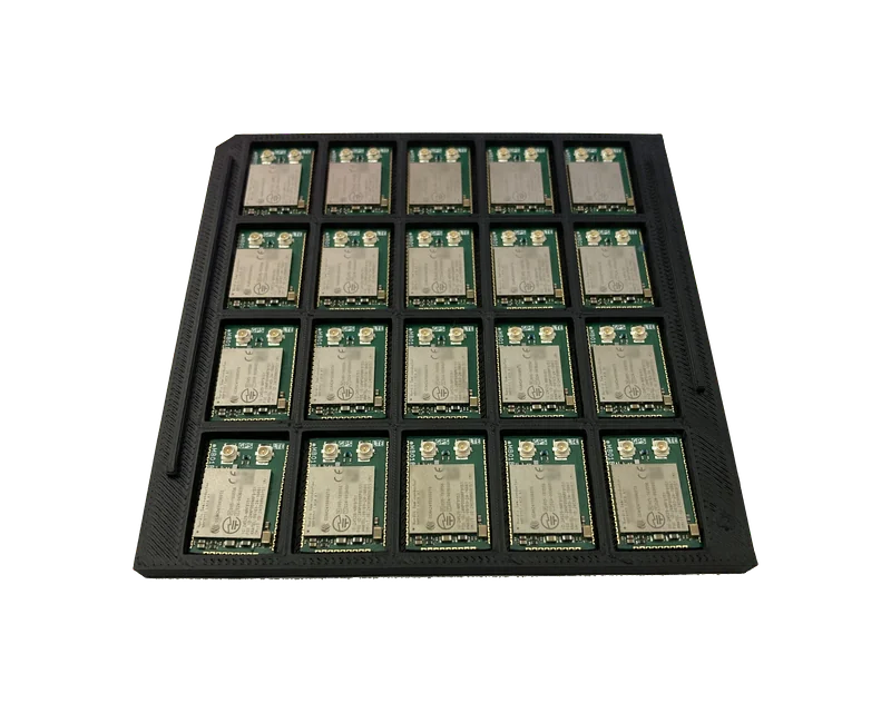
The nRF9151 Micro Breakout can be supplied in volume to customers integrating it into their own products. Modules ship in stackable trays, are individually tested, and arrive with per-unit test data referenced to tray position.
- Any volume — prototype quantities through to full production
- Every unit individually tested on a production fixture
- Test data mapped to tray position, supplied as PDF and CSV
- Full pick data published for automated placement
- Static-dissipative trays for long-term storage and transit
- Custom tray configurations available
Ordering
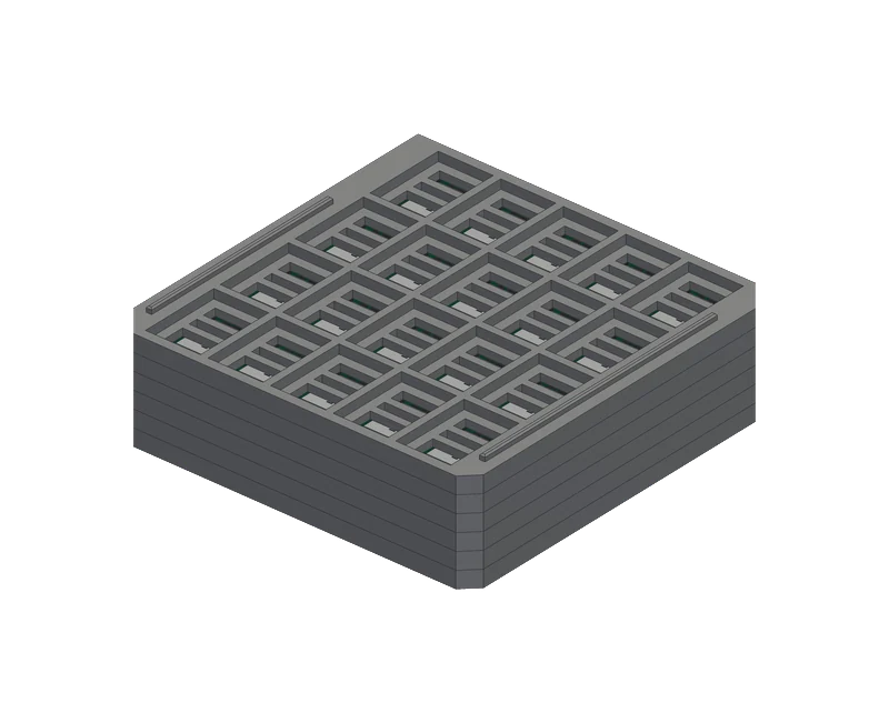
There is no minimum order quantity. Standard packing is 20 units per tray with up to 10 trays per stack; a quantity that does not fill a tray is shipped part-filled.
Trays are identical and self-stacking — there is no lid and no second part. A raised rail on each side drops into a matching groove in the underside of the tray above, and the rails are asymmetric along their length, so a tray turned through 180° will not seat.
Trays are produced from a parametric model rather than a hard tool, so the pocket matrix, pitch and outline can be adapted to a customer's handling equipment without tooling cost or lead time. If the standard 5 × 4 tray does not suit your line, talk to us about a variant.
| Property | Value |
|---|---|
| Outline | 96.50 × 97.00 mm |
| Height | 6.00 mm overall; 4.50 mm stack pitch |
| Matrix | 4 rows (A–D) × 5 columns (1–5) = 20 pockets |
| Material | Static-dissipative ABS (ABS-ESD), black |
Tray positions
Pocket A1 is identified by the single 45° chamfered corner, cut through the full height of the tray. With the chamfer at the top left in plan view, rows run A to D from the chamfered end and columns 1 to 5 from the chamfered side.
| 1 | 2 | 3 | 4 | 5 | |
|---|---|---|---|---|---|
| A | A1 | A2 | A3 | A4 | A5 |
| B | B1 | B2 | B3 | B4 | B5 |
| C | C1 | C2 | C3 | C4 | C5 |
| D | D1 | D2 | D3 | D4 | D5 |
Modules are loaded components up, with the plain edge — the short edge with U.FL connectors — toward row A. Trays are filled from A1 in row-major order; the quantity on the label is authoritative where a tray is part-filled.
Test data
Every unit is programmed and validated individually on a production test fixture before shipping. A unit that fails is not shipped and never enters the log.
Each batch is supplied with a test manifest as PDF and optionally CSV:
| Field | Content |
|---|---|
| Verdict | PASS badge per unit |
| Position | Tray number and grid position, A1 through D5 |
| Identifiers | IMEI as text and Code 128 barcode, device UUID, die ID |
| Test results | LTE registration, DNS resolution, TCP connection, GNSS fix |
| Timing | Time to first fix (TTFF) |
| Machine-readable | Per-unit QR code; CSV carries tray and position columns |
This is what makes volume ordering straightforward at your incoming inspection: a specific unit can be located in a specific pocket without unpacking the batch, and its identifiers checked against the manifest before it reaches your line.
Position data is advisory
The position map records the pocket each module occupied when packed. It is not a guarantee of placement order, because automated processes may discard, re-pick or reject units. The authoritative identification of any individual module is the device UUID, read electronically at your functional test — a binding that is immune to packaging order.
Automated placement
The tray presents modules on a regular, known matrix at a fixed pitch, which suits direct picking. Full pick data is published for programming placement equipment.
The pick point is not the package centre
The pick surface is the shield can, and the can is not concentric with the package outline. A nozzle centred on the package outline sits 1.97 mm off the pick point, and anything overhanging the can lands on the U.FL connectors, which stand 0.094 mm proud of the pick surface. The same offset applies to every pocket, so a single correction covers the tray.
These are not JEDEC matrix trays and provide no tray-changer or fixturing features. The first pick position is taught and the matrix indexes from it; trays picked from directly should be located and retained on the machine bed. Where this does not suit an existing line, modules can equally be transferred to your own carrier, or a custom tray produced.
Enquiries
For volume pricing, lead times or a custom tray configuration, contact us at hello@iscatek.com.